Drawings
 90
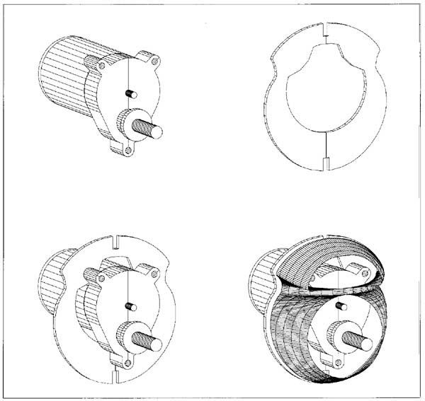
percent of the Super Guppy was built inside the computer before one piece
of wood was cut. This series of drawings were needed to check for any interference
between the cowl and the gearbox. First the motor and gearbox had to be
measured and drawn. They were the put into place on the firewall, then the
cowl was put in it's place. DesignCad 3d has an interference tool especially
made for this situation. Some was found and the firewall was pushed back
in the design stage before it was built. From a scratch-builders perspective,
this has proved itself to be a well thought out design. Special attention
was paid during the "kitting" of the model, from the measuring
the size (a one inch square was added to all drawings and measured as it
was coming out of the printer) of all plans and part sheets, to the cutting
of all wood parts that were to become a Guppy.
90
percent of the Super Guppy was built inside the computer before one piece
of wood was cut. This series of drawings were needed to check for any interference
between the cowl and the gearbox. First the motor and gearbox had to be
measured and drawn. They were the put into place on the firewall, then the
cowl was put in it's place. DesignCad 3d has an interference tool especially
made for this situation. Some was found and the firewall was pushed back
in the design stage before it was built. From a scratch-builders perspective,
this has proved itself to be a well thought out design. Special attention
was paid during the "kitting" of the model, from the measuring
the size (a one inch square was added to all drawings and measured as it
was coming out of the printer) of all plans and part sheets, to the cutting
of all wood parts that were to become a Guppy.(30K JPG image)
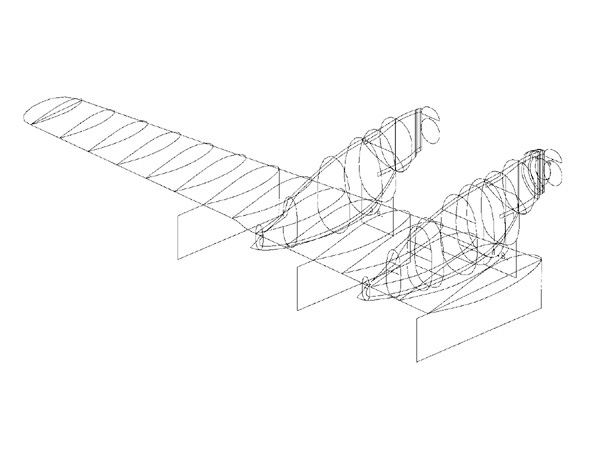
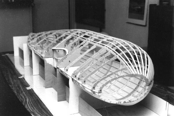
 At
this stage of constructing the virtual-Guppy, the outllines have been traced
from the scanned bit-mapped image, and into vector format. This allows for
the rotation and final placement of all outlines. All of the major bulkheads
and ribs have been located in their proper location and orientation. The
next job is applying the skin. By selecting the correct number of vertical
and horizontal breaks, DesignCad creates the wing ribs in place and the
correct size, ready to be traced.
At
this stage of constructing the virtual-Guppy, the outllines have been traced
from the scanned bit-mapped image, and into vector format. This allows for
the rotation and final placement of all outlines. All of the major bulkheads
and ribs have been located in their proper location and orientation. The
next job is applying the skin. By selecting the correct number of vertical
and horizontal breaks, DesignCad creates the wing ribs in place and the
correct size, ready to be traced. (35K JPG image)
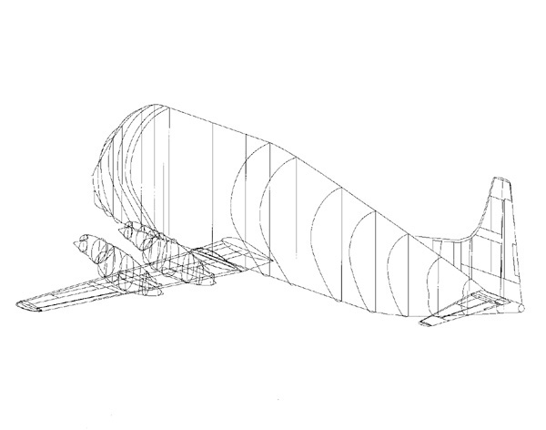
 All of the jigs needed for proper alignment and decalage of the model were
built in the same manner. First all unneeded layers were turned off, then
an imaginary floor was temporarily put into place in the form of a plane.
Then using the rib or bulkhead outline for the top of the jig, vertical
lines were connected between the outline and the floor.
All of the jigs needed for proper alignment and decalage of the model were
built in the same manner. First all unneeded layers were turned off, then
an imaginary floor was temporarily put into place in the form of a plane.
Then using the rib or bulkhead outline for the top of the jig, vertical
lines were connected between the outline and the floor.(38K JPG image)
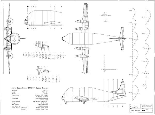 This
is Dan's magnificent 3-view of the Aero Spacelines 377SGT Super Guppy Turbine.
Dan drew these after the model built, and from the original virtual-Guppy
he built. An experienced builder could propably build their own Guppy from
these drawings. Dan was very complete in his drawings. He included all bulkheads;
this is not seen in many 3-view drawings.
This
is Dan's magnificent 3-view of the Aero Spacelines 377SGT Super Guppy Turbine.
Dan drew these after the model built, and from the original virtual-Guppy
he built. An experienced builder could propably build their own Guppy from
these drawings. Dan was very complete in his drawings. He included all bulkheads;
this is not seen in many 3-view drawings.(37K JPG image)
Pictures
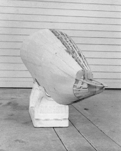
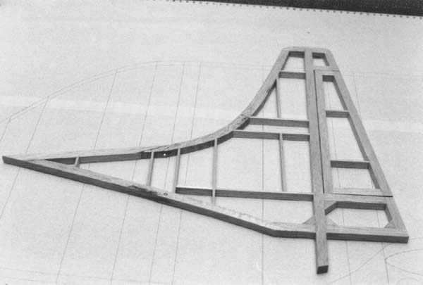 The
vertical fin and rudder has been pulled up from the "building board".
This picture was taken before sanding the fin and rudder. The rudder was
tapered to the trailing edge, sanded flat so as to minimize any "starved
horse" look when covered, while the fin was left flat only rounding
the the leading edge, with the dorsal fin tapering to a point at the front.
The unusual construction of ribs was done to simulate the panel lines of
the full size Super Guppy, and no sheeting was used in an effort to keep
the model as light as possible.
The
vertical fin and rudder has been pulled up from the "building board".
This picture was taken before sanding the fin and rudder. The rudder was
tapered to the trailing edge, sanded flat so as to minimize any "starved
horse" look when covered, while the fin was left flat only rounding
the the leading edge, with the dorsal fin tapering to a point at the front.
The unusual construction of ribs was done to simulate the panel lines of
the full size Super Guppy, and no sheeting was used in an effort to keep
the model as light as possible.(20K JPG image)
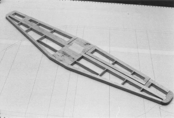 Both
the vertical and horizontal tail surfaces were built using 1/2 inch thick
contest balsa. The stabilizer and elevator were first tapered from 1/2 inch
at the root to 1/4 inch at the tips (from 1/4 inch either side of the centerline
to 1/8 inch either side of the centerline respectively). Then the elevator
was tapered from the main stab spar to the trailing edge of the elevator.
Again block sanding flat to minimize any fabric sag. The ribs were again
placed on the scale panel line location.
Both
the vertical and horizontal tail surfaces were built using 1/2 inch thick
contest balsa. The stabilizer and elevator were first tapered from 1/2 inch
at the root to 1/4 inch at the tips (from 1/4 inch either side of the centerline
to 1/8 inch either side of the centerline respectively). Then the elevator
was tapered from the main stab spar to the trailing edge of the elevator.
Again block sanding flat to minimize any fabric sag. The ribs were again
placed on the scale panel line location.(21K JPG image)
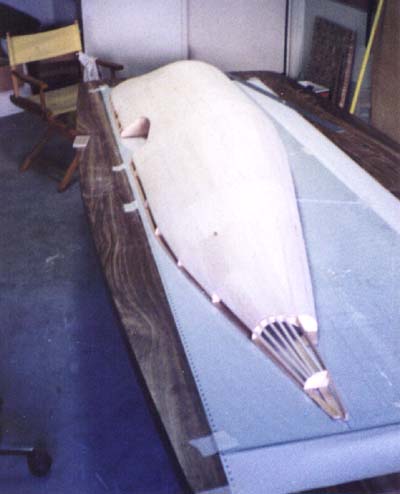
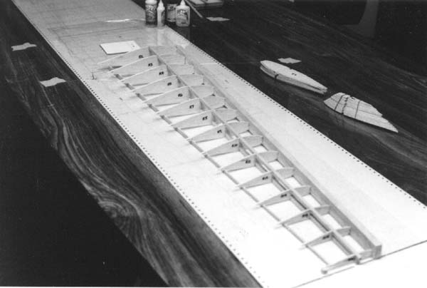
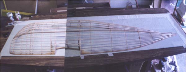 The conference table that was used for the construction of the Super Guppy
measures approx. 4 ft. by 8 ft. The plans were laid down on the table and
glass was laid down over the plans. Kitchen plastic wrap was put over the
glass to keep the parts from sticking too well to the glass. The plastic
wrap is the actual building surface. The top and bottom keels were glued
into place first, then using a tall square, the bulkheads were one by one
glued onto the keels. The side keels were dry fit into place first, helping
to hold the bulkheads square and flat, then glued. All of the stringers
first had to be spliced before being rag-soaked with water (at 8 ft. they
were too long for the bathtub) to soften the wood for bending around the
nose of the Guppy. As can be seen, the fuselage takes up the most of the
table.
The conference table that was used for the construction of the Super Guppy
measures approx. 4 ft. by 8 ft. The plans were laid down on the table and
glass was laid down over the plans. Kitchen plastic wrap was put over the
glass to keep the parts from sticking too well to the glass. The plastic
wrap is the actual building surface. The top and bottom keels were glued
into place first, then using a tall square, the bulkheads were one by one
glued onto the keels. The side keels were dry fit into place first, helping
to hold the bulkheads square and flat, then glued. All of the stringers
first had to be spliced before being rag-soaked with water (at 8 ft. they
were too long for the bathtub) to soften the wood for bending around the
nose of the Guppy. As can be seen, the fuselage takes up the most of the
table.(19K JPG image)
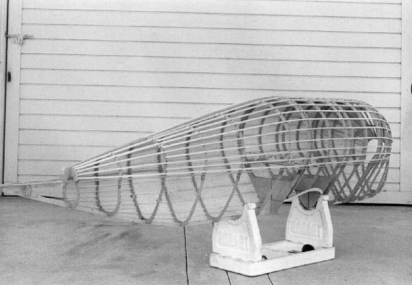
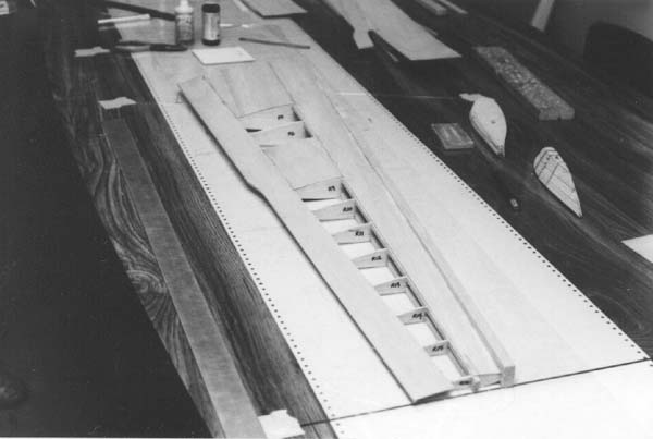
 3/16 square stock contest balsa was selcted for the stringers as the best
compromise between weight to strength ratio. Before the fuselage was sheeted,
it was sanded just enough to smooth all bulkhead to stringer joints. 1/32
contest balsa was used to sheet the fuselage. We decided to sheet the left
half of the fuselage in an attempt to keep it as straight as possible after
pulling the fuselage up from the building board. The very top and bottom
bays and the tail section of the fuselage were left unsheeted until last
in case any access was needed later. This actually worked very well, the
fuselage didn't warp at all. It did however look like a odd shaped canoe
when flipped open side up.
3/16 square stock contest balsa was selcted for the stringers as the best
compromise between weight to strength ratio. Before the fuselage was sheeted,
it was sanded just enough to smooth all bulkhead to stringer joints. 1/32
contest balsa was used to sheet the fuselage. We decided to sheet the left
half of the fuselage in an attempt to keep it as straight as possible after
pulling the fuselage up from the building board. The very top and bottom
bays and the tail section of the fuselage were left unsheeted until last
in case any access was needed later. This actually worked very well, the
fuselage didn't warp at all. It did however look like a odd shaped canoe
when flipped open side up.(20K JPG image)
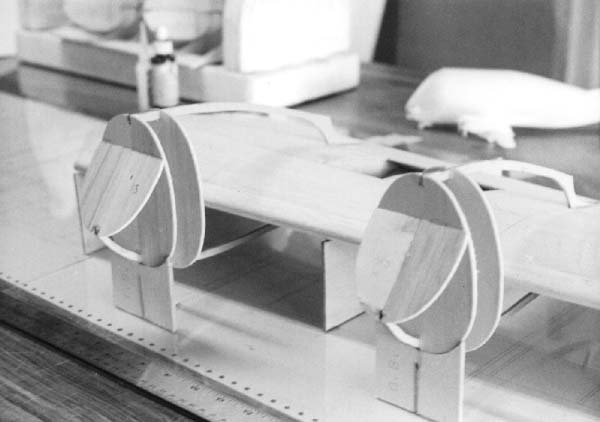
 The
fuselage jig was also designed in the computer. The fuselage was first rotated
90 degrees along the longitudinal axis. At each bulkhead station, Dan drew
a box using the bulkhead outlines for the fuselage saddle, down to virtual
floor. Egg crate design was selected for it's simpicity. The jig was squared
and glued directly to the glass to help hold it in alignment. The fuselage
dropped right in like it was made for it. It was, but that's beside the
point. We later found that the jig worked so well in fact, that gluing either
the fuselage to the jig, or the jig to the table became unnecessary, and
the jig was used as a craddle for working on the fuselage.
The
fuselage jig was also designed in the computer. The fuselage was first rotated
90 degrees along the longitudinal axis. At each bulkhead station, Dan drew
a box using the bulkhead outlines for the fuselage saddle, down to virtual
floor. Egg crate design was selected for it's simpicity. The jig was squared
and glued directly to the glass to help hold it in alignment. The fuselage
dropped right in like it was made for it. It was, but that's beside the
point. We later found that the jig worked so well in fact, that gluing either
the fuselage to the jig, or the jig to the table became unnecessary, and
the jig was used as a craddle for working on the fuselage.(29K JPG image)
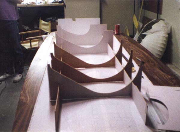
 The
Balsa Canoe! Actually the fuselage was constructed using 3mm, 3 ft. by 7
ft. mohogany plywood doorskins for all keels and bulkheads. We decided to
cut one piece keels rather than splice several smaller pieces together.
The bulkheads were cut from the doorskins also. We initially purchased the
plywood doorskins from a local HomeBase for about $7.00 each. Price was
a consideration, because we found during parts layout for cutting, it would
take at least 3 doorskins for the keels and bulkheads, not including the
fuselage jig, that took another doorskin. Here the fuselage jig is glued
down to the glass over the jig plans, and the fuselage has been put into
place and glued, with the top and bottom keels flush with the top of the
jig. The bulkheads were thinned from the intial design during cutting, as
it was decided that less material on the inboard side (away from the stringers)
would still retain enough strength, and would save weight.
The
Balsa Canoe! Actually the fuselage was constructed using 3mm, 3 ft. by 7
ft. mohogany plywood doorskins for all keels and bulkheads. We decided to
cut one piece keels rather than splice several smaller pieces together.
The bulkheads were cut from the doorskins also. We initially purchased the
plywood doorskins from a local HomeBase for about $7.00 each. Price was
a consideration, because we found during parts layout for cutting, it would
take at least 3 doorskins for the keels and bulkheads, not including the
fuselage jig, that took another doorskin. Here the fuselage jig is glued
down to the glass over the jig plans, and the fuselage has been put into
place and glued, with the top and bottom keels flush with the top of the
jig. The bulkheads were thinned from the intial design during cutting, as
it was decided that less material on the inboard side (away from the stringers)
would still retain enough strength, and would save weight.(20K JPG image)
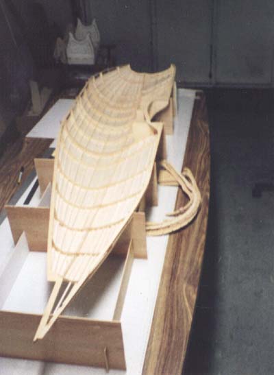
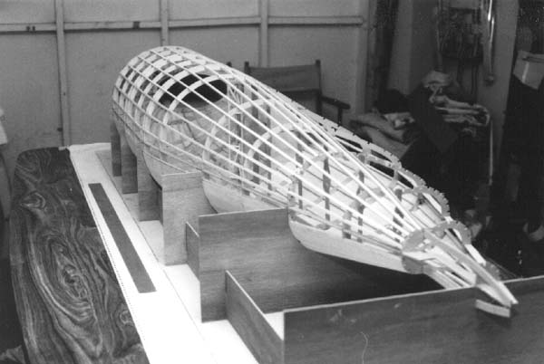
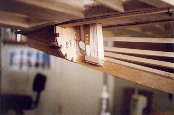
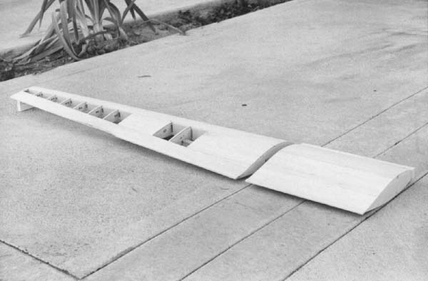
 Here
the fuselage is seen with the starboard side bulkheads, side keel and upper
stringers. The lower stringers were left off temporarily for access to the
inside of the fuselage. At this point, the fuselage can be pulled out of
the jig and checked for warps in the fuselage. Some elements of the actual
engineering, such as where to put the battery pack and how to mount it,
the nosewheel mount and steering set-up, and the mounting of tail surface
servos was not done in the computer, as we decided this type of work is
more expediant if done in the real world.
Here
the fuselage is seen with the starboard side bulkheads, side keel and upper
stringers. The lower stringers were left off temporarily for access to the
inside of the fuselage. At this point, the fuselage can be pulled out of
the jig and checked for warps in the fuselage. Some elements of the actual
engineering, such as where to put the battery pack and how to mount it,
the nosewheel mount and steering set-up, and the mounting of tail surface
servos was not done in the computer, as we decided this type of work is
more expediant if done in the real world.(31K JPG image)
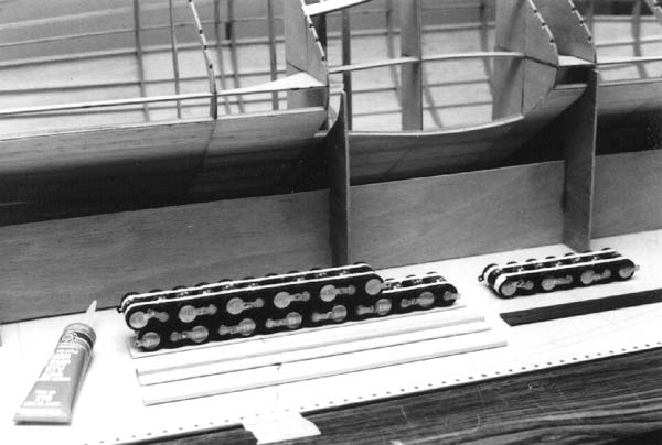 We
initially purchased 32 Sanyo 1700 mah SCRC sub C-cell batteries, not knowing
whether it would take 7 or 8 cells per motor to fly the Guppy. After motor
and prop testing we decided that given the power to weight ratio, the extra
8.8 ounces in battery weight (2.2 ounces per cell), didn't provide enough
additional thrust to push that weight through the air. The battery cells
were first laid out on the bench on top of two strips of masking tape. The
tape was used to hold the cells in alignment for soldering. Once we had
two 14 cell sticks (actually, we built the battery pack with fourteen cells
on one side, and eleven on the other, leaving one end of the battery pack
open for later installation of either 3 or 7 cells, depending on the motor/prop
test results), a four sided box was built around the battery pack using
1/8 inch balsa sheet. The masking tape was removed and the box sides were
glued to the battery pack using silicon RTV. One hardwood rail was fitted
to each side of the box. We decided to make the battery pack removable for
charging, so a simple drawer design with a rear stop and front retaining
pins was adopted.
We
initially purchased 32 Sanyo 1700 mah SCRC sub C-cell batteries, not knowing
whether it would take 7 or 8 cells per motor to fly the Guppy. After motor
and prop testing we decided that given the power to weight ratio, the extra
8.8 ounces in battery weight (2.2 ounces per cell), didn't provide enough
additional thrust to push that weight through the air. The battery cells
were first laid out on the bench on top of two strips of masking tape. The
tape was used to hold the cells in alignment for soldering. Once we had
two 14 cell sticks (actually, we built the battery pack with fourteen cells
on one side, and eleven on the other, leaving one end of the battery pack
open for later installation of either 3 or 7 cells, depending on the motor/prop
test results), a four sided box was built around the battery pack using
1/8 inch balsa sheet. The masking tape was removed and the box sides were
glued to the battery pack using silicon RTV. One hardwood rail was fitted
to each side of the box. We decided to make the battery pack removable for
charging, so a simple drawer design with a rear stop and front retaining
pins was adopted.(33K JPG image)
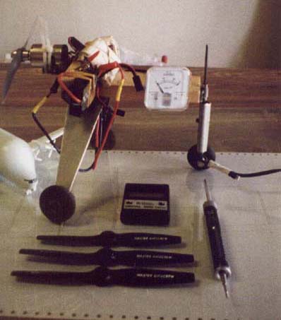 This is our low tech motor test stand. It looks crude, but it provided us
with some very crucial data. Seen here starting with the stand itself, is
the duel purpose motor mount, used for both the electric motors and an O.S.
15FP during baseline testing. The O.S. 15 with a 8x4 APC prop developed
1-1/2 lbs. of thrust at 11,000 RPM. This was the minium amount of thrust
we thought would be needed to safely fly the Guppy. In order to achieve
the most accurate results, we mounted all radio gear(receiver, airborne
battery pack, switch harness, 7 or 8 cell 1700 mAmp motor battery pack,
and speed controller w/fuse) on the stand. We also mounted a amp meter,
and volt meter to the stand.
This is our low tech motor test stand. It looks crude, but it provided us
with some very crucial data. Seen here starting with the stand itself, is
the duel purpose motor mount, used for both the electric motors and an O.S.
15FP during baseline testing. The O.S. 15 with a 8x4 APC prop developed
1-1/2 lbs. of thrust at 11,000 RPM. This was the minium amount of thrust
we thought would be needed to safely fly the Guppy. In order to achieve
the most accurate results, we mounted all radio gear(receiver, airborne
battery pack, switch harness, 7 or 8 cell 1700 mAmp motor battery pack,
and speed controller w/fuse) on the stand. We also mounted a amp meter,
and volt meter to the stand.This left us with a free-rolling unit which we were able to test volts, amp draw, RPM, thrust and duration. Since the electric power is clean and quiet, all testing with electric motors was done in the author's garage on the glass covered table for the least amount of rolling resistance(about 2 grams start-up, and 1 gram constant under load). Also seen is the tachometer for measuring RPM, simple spring scale(gradiated in grams), and various props tested. The "tailwheel" has a safety line attached, with the other end tied to a heavy tool box.
(22K JPG image)
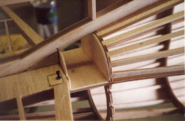
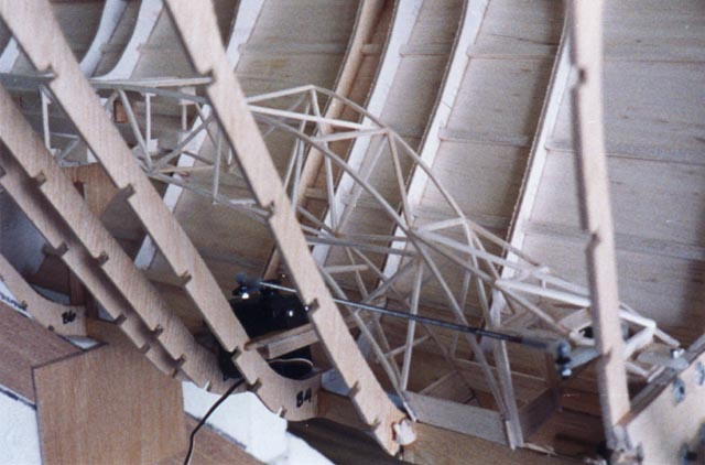
 Because
of space considerations during transport to and from the flying field, the
Guppy's tail needed to be removable. Seen in this photo is the initial engineering
for tail surface actuation. Note the cross members in the rear fuselage
for the push-pull tubes. This idea was later scrapped in favor of free floating
pushrods, again for the reasons of weight and simplicity. The support necessary
for the push-pull tubes and inner pushrods didn't provide enough flexibility
to lift the tail section up enough to connect and disconnect the connectors
from the tail surfaces, and added too much extra weight.
Because
of space considerations during transport to and from the flying field, the
Guppy's tail needed to be removable. Seen in this photo is the initial engineering
for tail surface actuation. Note the cross members in the rear fuselage
for the push-pull tubes. This idea was later scrapped in favor of free floating
pushrods, again for the reasons of weight and simplicity. The support necessary
for the push-pull tubes and inner pushrods didn't provide enough flexibility
to lift the tail section up enough to connect and disconnect the connectors
from the tail surfaces, and added too much extra weight.(30K JPG image)
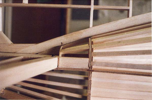
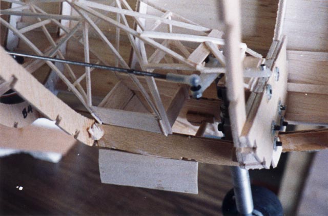
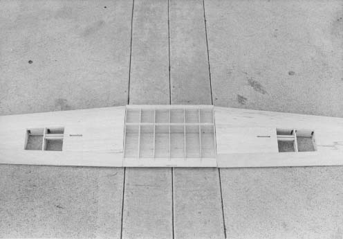
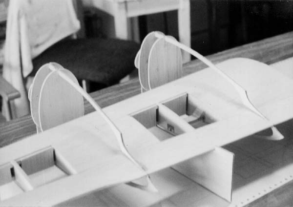
 The
fuselage at this point weights about 1-1/2 lbs. It took a while to get used
to the lack of weight. We futher reduced the fuselage's weight by cutting
lightening holes in the 5 wing saddle bulkheads. Experience has shown that
to build a light model airplane, one needs to save a little weight every
step along the way. Every little bit helps. Notice that the push-pull tube
supports are gone. It was decided to keep the "girder" servo tray,
we would be able to run the pushrods from their existing location, back
to the tail.
The
fuselage at this point weights about 1-1/2 lbs. It took a while to get used
to the lack of weight. We futher reduced the fuselage's weight by cutting
lightening holes in the 5 wing saddle bulkheads. Experience has shown that
to build a light model airplane, one needs to save a little weight every
step along the way. Every little bit helps. Notice that the push-pull tube
supports are gone. It was decided to keep the "girder" servo tray,
we would be able to run the pushrods from their existing location, back
to the tail.(29K JPG image)
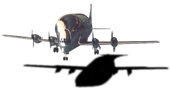
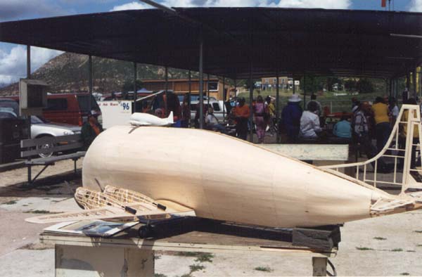
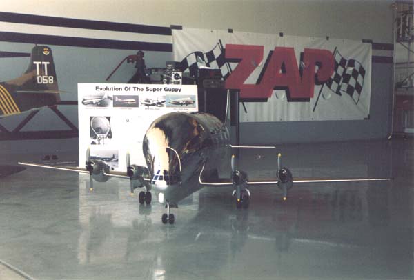
 From
this angle, the size and unusual shape of the fuselage is more apparent.
Neighbors often wondered what type of blimp we were building. Luckily there
was always a picture of the full-size Super Guppy on take-off hanging on
the wall, to inspire us, and show the neighbors what we were building a
model of. This began a trend that took both Dan and me by surprise, and
continued the entire life of the Guppy. Everybody had a "Guppy Story".
Or so it seemed. Many remember seeing the Pregnant Guppy flying in and out
of Long Beach airport as children in the 60's. One guy's dad worked for
Aero Spacelines, and he remembers as a kid 9 or 10 years old, playing on
the Pregnant Guppy while they were building it. And we thought we'd picked
a relatively obscure airplane to model.
From
this angle, the size and unusual shape of the fuselage is more apparent.
Neighbors often wondered what type of blimp we were building. Luckily there
was always a picture of the full-size Super Guppy on take-off hanging on
the wall, to inspire us, and show the neighbors what we were building a
model of. This began a trend that took both Dan and me by surprise, and
continued the entire life of the Guppy. Everybody had a "Guppy Story".
Or so it seemed. Many remember seeing the Pregnant Guppy flying in and out
of Long Beach airport as children in the 60's. One guy's dad worked for
Aero Spacelines, and he remembers as a kid 9 or 10 years old, playing on
the Pregnant Guppy while they were building it. And we thought we'd picked
a relatively obscure airplane to model.(20K JPG image)
Saving weight a little here and a little there meant building up the filler block needed to complete fuselage.
(31K, 32K & 27K JPG images)
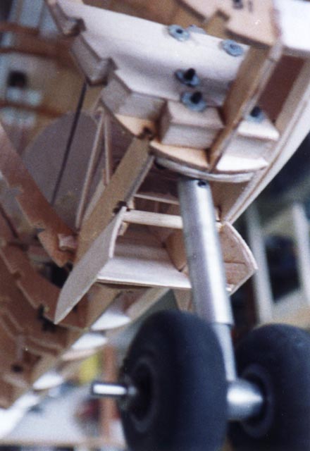
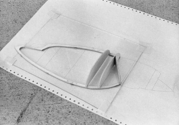
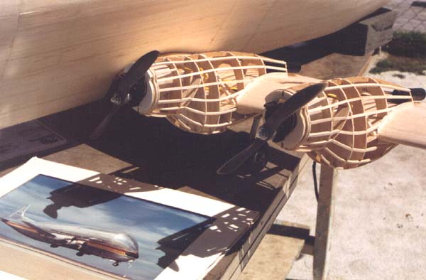
This series of pictures show the construction detail of the nose gear and cooling scoop incorporated into the nose gear doors as seen in the first picture. This frame work for the cooling ducting looks admittedly a bit strange, but it was built with weight and funtionality in mind. It had to direct the cooling air over the batteries in flight and be able to be removed without any tools to get the battery pack out of the airplane for charging. The third picture shows how the ducting was built around the nose gear steering pushrod. The last picture in this series shows the finished cooling duct with it's tissue paper covering. This was sealed with two coats of dope. Also seen is the nose wheel servo and battery rails and battery pack support. The nose, ducting and battery pack were all designed to be removed without tools. The lower scoop was also designed to be removable, but it was bolted into place using only one screw.
(40K, 52K, 48K & 46K JPG images)
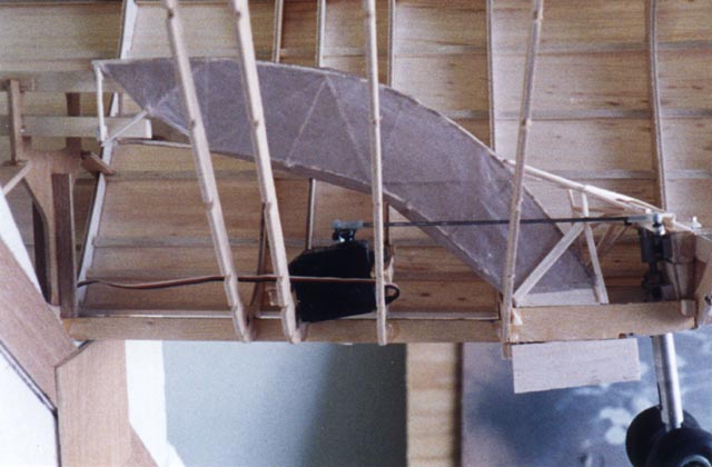
 The
wing was built using the same glass over plans method. This stage of construction
is very conventional. Contest balsa was used for the entire wing structure.
As this was a prototype, certain changes would be made in future models,
such as replacing the 3/8 inch square balsa spars with the same size in
basswood or light spruce, and full length 1/64 or 1/32 plywood rib doublers
at the landing gear station ribs instead of the half doublers used. The
ribs are jigged up with a piece of 3/16 square strip stock, sighted from
the tip to the root for alignment, and glued. The leading edge has been
installed as well as the top spar. The wing is now ready for sheeting.
The
wing was built using the same glass over plans method. This stage of construction
is very conventional. Contest balsa was used for the entire wing structure.
As this was a prototype, certain changes would be made in future models,
such as replacing the 3/8 inch square balsa spars with the same size in
basswood or light spruce, and full length 1/64 or 1/32 plywood rib doublers
at the landing gear station ribs instead of the half doublers used. The
ribs are jigged up with a piece of 3/16 square strip stock, sighted from
the tip to the root for alignment, and glued. The leading edge has been
installed as well as the top spar. The wing is now ready for sheeting.(24K JPG image)
 The
leading edge sheeting has been added, and the trailing edge core sheeting
has been fit into place. The wing is built upright on the "building
board", saving the bottom sheeting until after the landing gear blocks
and wiring tubes for the servo extentions have been installed. Seen in the
background, is are the other wing section's ribs and trailing edge sheeting.
We felt that it would be lighter and easier in the long run to build up
the ailerons rather than use commercially available solid balsa trailing
edge stock. Because the design uses scale profiles throughout, including
wing planform and reflex airfoil shape, sanding or planing the ailerons
seemed like it would be more work. This proved to be true.
The
leading edge sheeting has been added, and the trailing edge core sheeting
has been fit into place. The wing is built upright on the "building
board", saving the bottom sheeting until after the landing gear blocks
and wiring tubes for the servo extentions have been installed. Seen in the
background, is are the other wing section's ribs and trailing edge sheeting.
We felt that it would be lighter and easier in the long run to build up
the ailerons rather than use commercially available solid balsa trailing
edge stock. Because the design uses scale profiles throughout, including
wing planform and reflex airfoil shape, sanding or planing the ailerons
seemed like it would be more work. This proved to be true.(25K JPG image)
 The
trailing edge sheeting has been added, as well as the inboard center sheeting
and the outer sheeting planned for the base of the outboard engine nacelles.
The wing is now ready for capstrips on the ribs. One of the benefits of
electric powered models is the almost no vibration, this translates into
being able to use much lighter structures on the airframe, since all "wet"
power designs must be able to absorb the vibration of the engine.
The
trailing edge sheeting has been added, as well as the inboard center sheeting
and the outer sheeting planned for the base of the outboard engine nacelles.
The wing is now ready for capstrips on the ribs. One of the benefits of
electric powered models is the almost no vibration, this translates into
being able to use much lighter structures on the airframe, since all "wet"
power designs must be able to absorb the vibration of the engine.(22K JPG image)
 It
looks a lot like a wing for a glider. Actually, the wing turned out light
enough to be used on glider. We found ourselves constantly reassuring each
other that "the wing area doesn't tell the whole story". It was
a high-aspect, thick chord with a fair amount of reflex on the top portion
of the airfoil. The B-29 was designed to carry a heavy load effiecently.
We hoped that some of the characteristics would stay with the wing when
scaled down. And we figured on some lift from the fuselage, though where
and how much we had no way of guessing.
It
looks a lot like a wing for a glider. Actually, the wing turned out light
enough to be used on glider. We found ourselves constantly reassuring each
other that "the wing area doesn't tell the whole story". It was
a high-aspect, thick chord with a fair amount of reflex on the top portion
of the airfoil. The B-29 was designed to carry a heavy load effiecently.
We hoped that some of the characteristics would stay with the wing when
scaled down. And we figured on some lift from the fuselage, though where
and how much we had no way of guessing.(25K JPG image)
 Seen here is the bottom of the wing. The landing gear blocks have been installed,
and both wing panels have been completely sheeted and sanded awaiting mounting
of the engine nacelles. The wing center section still needs to have the
shear webs installed and bottom sheeting fit and glued.
Seen here is the bottom of the wing. The landing gear blocks have been installed,
and both wing panels have been completely sheeted and sanded awaiting mounting
of the engine nacelles. The wing center section still needs to have the
shear webs installed and bottom sheeting fit and glued.(18K JPG image)
 The
majority of the detail construction would be done before joining the wing
panels. We began with the engine nacelles. The nacelles were constructed
in much the same manner as the rest of the airplane, with plastic wrap over
glass taped to the plans serving as the building surface. Because the inner
and outer nacelles are different, only two sets of bulkheads could be cut
at one time. The keels were cut individually as extra care was needed at
the rear because of a very shallow taper. The bulkheads were all contest
grade balsa and the keels were cut from the copious amounts of scrap plywood
this project generated.
The
majority of the detail construction would be done before joining the wing
panels. We began with the engine nacelles. The nacelles were constructed
in much the same manner as the rest of the airplane, with plastic wrap over
glass taped to the plans serving as the building surface. Because the inner
and outer nacelles are different, only two sets of bulkheads could be cut
at one time. The keels were cut individually as extra care was needed at
the rear because of a very shallow taper. The bulkheads were all contest
grade balsa and the keels were cut from the copious amounts of scrap plywood
this project generated.(26K JPG image)
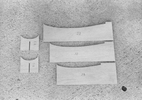 Seen
here are the wing and nacelle jigs. Missing from this photo are the triangle
braces for the nacelle jigs. Having these jigs proved invaluable when it
came time for the rebuilds after the crashes a prototype seems to endure.
The same jigs were used throughout, and will be again for all future Guppys
we build. As with all parts cut during the "kitting" phase of
the project, care was taken to get consistant cuts as a test of the computer's
rendition of Dan's design. And here, like all other parts, the fit was perfect.
Seen
here are the wing and nacelle jigs. Missing from this photo are the triangle
braces for the nacelle jigs. Having these jigs proved invaluable when it
came time for the rebuilds after the crashes a prototype seems to endure.
The same jigs were used throughout, and will be again for all future Guppys
we build. As with all parts cut during the "kitting" phase of
the project, care was taken to get consistant cuts as a test of the computer's
rendition of Dan's design. And here, like all other parts, the fit was perfect.(41K JPG image)
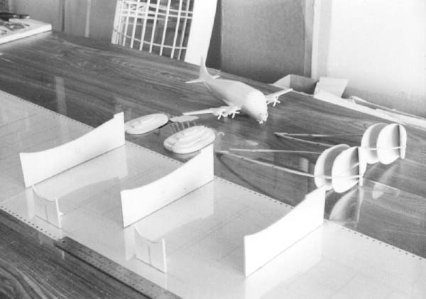 The
plastic model of the Super Guppy was always near at hand during construction
for reference. This model turned out to be surprisingly scale when compared
to pictures of the full size Guppy. Most medium to high quality plastic
models are a great source of scale documentation or ideas for the endless
"next" airplane to build. The wing jigs were glued in place over
the plans with the wing seated but not glued into place and a square was
used to align the wing over the plans. This assured the proper alignment
of the nacelles on the wing.
The
plastic model of the Super Guppy was always near at hand during construction
for reference. This model turned out to be surprisingly scale when compared
to pictures of the full size Guppy. Most medium to high quality plastic
models are a great source of scale documentation or ideas for the endless
"next" airplane to build. The wing jigs were glued in place over
the plans with the wing seated but not glued into place and a square was
used to align the wing over the plans. This assured the proper alignment
of the nacelles on the wing. (24K JPG image)
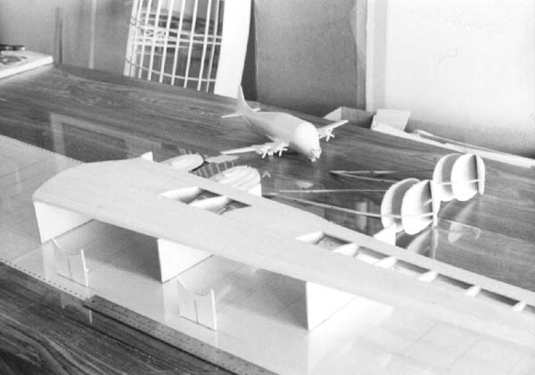 The
wing has now been glued into place on the jigs, and the nacelle jigs' placement
has been finalized. It was necessary to round and final sand the leading
edges of the wing for proper seating in the wing jigs. Also seen in the
background are the nacelles ready for attachment, having been built in the
previous construction step. We placed the jigs in their locations shown
here for the purpose of supporting the wing in the area needed, towards
the root, where the nacelles would be attached. No tip jigs were used at
all for this step in construction.
The
wing has now been glued into place on the jigs, and the nacelle jigs' placement
has been finalized. It was necessary to round and final sand the leading
edges of the wing for proper seating in the wing jigs. Also seen in the
background are the nacelles ready for attachment, having been built in the
previous construction step. We placed the jigs in their locations shown
here for the purpose of supporting the wing in the area needed, towards
the root, where the nacelles would be attached. No tip jigs were used at
all for this step in construction.(25K JPG image)
 The
nacelles were first dry-set into their jigs to check the fit. Where the
rear of the keels sat on the wing was the determining factor in the fore-aft
placement of the nacelles. After aligning the vertical centerline of the
nacelles to plumb, they were tack-glued onto the jigs. We also were able
to remove most of the minor warps from the plywood keels by carefully glueing
the rear of the keels to the wing surface. Another plus for electric multi-engine
models, is that no internal connecting structure is needed between the wing
and nacelles. No vibration, so surface glueing is plenty strong enough.
The
nacelles were first dry-set into their jigs to check the fit. Where the
rear of the keels sat on the wing was the determining factor in the fore-aft
placement of the nacelles. After aligning the vertical centerline of the
nacelles to plumb, they were tack-glued onto the jigs. We also were able
to remove most of the minor warps from the plywood keels by carefully glueing
the rear of the keels to the wing surface. Another plus for electric multi-engine
models, is that no internal connecting structure is needed between the wing
and nacelles. No vibration, so surface glueing is plenty strong enough.(21K JPG image)
 This
is one of the steps we decided would be done more easily in the real world.
Actually making working nacelles. We first stabilized the front portion
of the nacelles with a flat plate of balsa plywood (three pieces of 1/32
balsa glued together with the grains of the wood running perpendicular)
between the leading edge of the wing and rear of the second bulkhead. Two
braces were also added at this time from the outer edges of the balsa plate
and the top bulkhead-keel joint. This stabilized the nacelles enough for
the next step, the rest of the bulkheads and stringers. We changed the design
of the nacelles just after these pictures were taken. The original design
called for direct-drive motors to be clamped to two dowels protruding from
the front of the existing bulkheads. The Leasure gearboxes were made to
mount to a firewall with screws or bolts.
This
is one of the steps we decided would be done more easily in the real world.
Actually making working nacelles. We first stabilized the front portion
of the nacelles with a flat plate of balsa plywood (three pieces of 1/32
balsa glued together with the grains of the wood running perpendicular)
between the leading edge of the wing and rear of the second bulkhead. Two
braces were also added at this time from the outer edges of the balsa plate
and the top bulkhead-keel joint. This stabilized the nacelles enough for
the next step, the rest of the bulkheads and stringers. We changed the design
of the nacelles just after these pictures were taken. The original design
called for direct-drive motors to be clamped to two dowels protruding from
the front of the existing bulkheads. The Leasure gearboxes were made to
mount to a firewall with screws or bolts.(19K JPG image)
 Our
solution was simple, just tack on top and bottom keel extentions, add a
couple of more bulkheads in front of the existing ones and add stringers.
The firewall was cut out of scrap doorskin and glued to the front of the
balsa firewall. The hole for the motor was cut and blind nuts were installed
on the rear of the firewall before gluing the firewall into place. All cooling
holes were cut in the remaining bulkheads before glueing in them into place.
The white tube in the front of the nacelle is made from printer paper rolled
into a one layer tube, and tack-glued into place with thin CA. The thin
CA wicks into the paper very nicely and becomes almost like a very thin
plywood. The rear cooling exhaust tube was made from black paper. The hollow
bulkheads were necessary because the cooling air the motors were going to
receive would come via a pressure cowl arraignment.
Our
solution was simple, just tack on top and bottom keel extentions, add a
couple of more bulkheads in front of the existing ones and add stringers.
The firewall was cut out of scrap doorskin and glued to the front of the
balsa firewall. The hole for the motor was cut and blind nuts were installed
on the rear of the firewall before gluing the firewall into place. All cooling
holes were cut in the remaining bulkheads before glueing in them into place.
The white tube in the front of the nacelle is made from printer paper rolled
into a one layer tube, and tack-glued into place with thin CA. The thin
CA wicks into the paper very nicely and becomes almost like a very thin
plywood. The rear cooling exhaust tube was made from black paper. The hollow
bulkheads were necessary because the cooling air the motors were going to
receive would come via a pressure cowl arraignment.(44K JPG image)
 This
series of pictures was taken at a giant scale fun-fly in Lake Elsinore,
California. We were very pleased with the way the Guppy was turning out.
The warm reception we received at this fly-in helped fuel our desire to
see the project through to the end. By comparing our Guppy to the plastic
model, it was easy to see the lines were correct. Using scale outlines throughout
the entire model was paying off. All of the angles of our Guppy matched
the plastic model and pictures of the full size Super Guppy when viewed
from any direction.
This
series of pictures was taken at a giant scale fun-fly in Lake Elsinore,
California. We were very pleased with the way the Guppy was turning out.
The warm reception we received at this fly-in helped fuel our desire to
see the project through to the end. By comparing our Guppy to the plastic
model, it was easy to see the lines were correct. Using scale outlines throughout
the entire model was paying off. All of the angles of our Guppy matched
the plastic model and pictures of the full size Super Guppy when viewed
from any direction.(37K JPG image)
 Although
the actual stringers and their slots weren't drawn in the computer, their
locations were. Dan first superimposed all of the nacelle bulkheads on top
of one another, once each for the inner and outer nacelles (the opposite
side was mirrored as a last step in the process). Once the bulkheads were
placed into their proper locations via a center mark, Dan was able to draw
a radius of lines were the stringers would go. This gave the stringers a
smooth, even flow from the front to the rear. The alignment marks were then
transferred to the bulkheads and stringer slots were cut centered on the
marks. The nacelle bulkheads' final placement was done via the trim and
fit method, but a final tracing was done of all nacelle bulkheads before
they were glued into place. With this job done, Dan invited me over to his
house for a "stringering" party. We used 1/8 inch square contest
grade balsa for all nacelle stringers.
Although
the actual stringers and their slots weren't drawn in the computer, their
locations were. Dan first superimposed all of the nacelle bulkheads on top
of one another, once each for the inner and outer nacelles (the opposite
side was mirrored as a last step in the process). Once the bulkheads were
placed into their proper locations via a center mark, Dan was able to draw
a radius of lines were the stringers would go. This gave the stringers a
smooth, even flow from the front to the rear. The alignment marks were then
transferred to the bulkheads and stringer slots were cut centered on the
marks. The nacelle bulkheads' final placement was done via the trim and
fit method, but a final tracing was done of all nacelle bulkheads before
they were glued into place. With this job done, Dan invited me over to his
house for a "stringering" party. We used 1/8 inch square contest
grade balsa for all nacelle stringers.(33K JPG image)
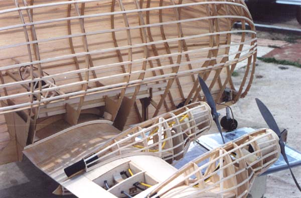
 From
this angle, it's easy to see the size disparity between the fuselage and
the wing. The wing fairing and belly pan were constructed after the fuselage
was fully sheeted. Many people we spoke with at later contests often remembered
seeing the Guppy at this fly-in, and were glad to see that we finished the
project. Everyone always expressed a desire to see the Guppy fly.
From
this angle, it's easy to see the size disparity between the fuselage and
the wing. The wing fairing and belly pan were constructed after the fuselage
was fully sheeted. Many people we spoke with at later contests often remembered
seeing the Guppy at this fly-in, and were glad to see that we finished the
project. Everyone always expressed a desire to see the Guppy fly.(32K JPG image)
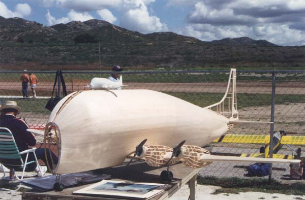
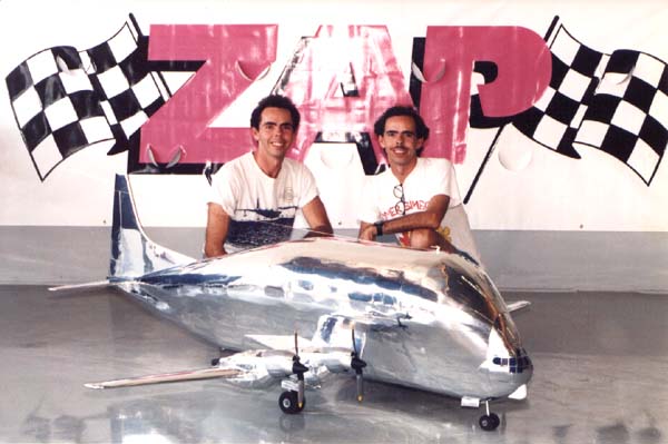
 Something
that was always a novelty for us, was the people standing in the background
staring at the model in disbelief. People would begin gathering as soon
as the wing with it's four nacelles was pulled out of the back of the truck,
followed by what at first glance, appears to be an odd shaped blimp. The
tail feathers were removable for transportation, giving us three major sub-components
( the wing, fuselage, and tail feathers), and two minor ones (belly pan
and nose cone) which when assembled, made up the Guppy. This is the Guppy's
first day at the flying field being prepared for the test flight.
Something
that was always a novelty for us, was the people standing in the background
staring at the model in disbelief. People would begin gathering as soon
as the wing with it's four nacelles was pulled out of the back of the truck,
followed by what at first glance, appears to be an odd shaped blimp. The
tail feathers were removable for transportation, giving us three major sub-components
( the wing, fuselage, and tail feathers), and two minor ones (belly pan
and nose cone) which when assembled, made up the Guppy. This is the Guppy's
first day at the flying field being prepared for the test flight.(32K JPG image)
 The Super Guppy is enduring a brief photo session before test flight. Although
the engine nacelles look small when compared to the fuselage, they are actually
about a foot long with the circumference of your average 40 size R/C model
airplane. If the nose of our model opened in a scale manner, four basketballs
would fit inside the fuselage with almost enough room for a fifth! This
is a good angle to see the world's simplest wing fairing. Also not seen
in any photos, the cooling exaust hole, is the dark area on the bottom of
the fuselage just as it angles up towards the tail.
The Super Guppy is enduring a brief photo session before test flight. Although
the engine nacelles look small when compared to the fuselage, they are actually
about a foot long with the circumference of your average 40 size R/C model
airplane. If the nose of our model opened in a scale manner, four basketballs
would fit inside the fuselage with almost enough room for a fifth! This
is a good angle to see the world's simplest wing fairing. Also not seen
in any photos, the cooling exaust hole, is the dark area on the bottom of
the fuselage just as it angles up towards the tail.(40K JPG image)
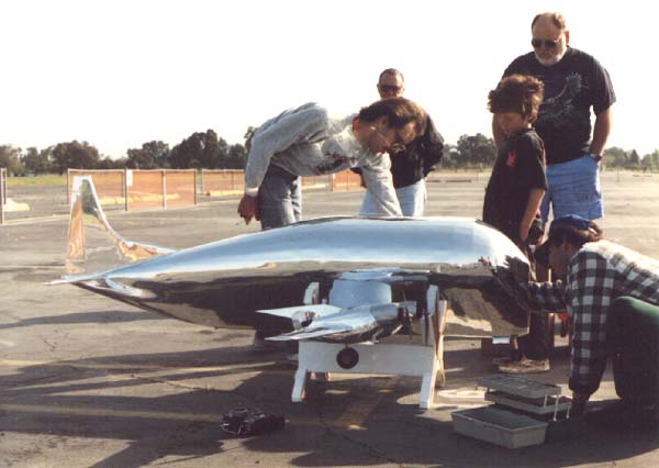
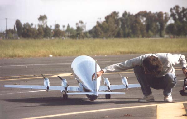 Dan's
checking for the amount of ground clearence. Even increasing the ground
clearence an inch by lengthening the landing gear struts and using larger
than scale wheels, we still only had three inches of ground clearence total
with the model at rest. The model would be limited to relatively flat take-offs
without dragging the tail during rotation prior to take-off. The shape and
height of the fuselage is seen very well here.
Dan's
checking for the amount of ground clearence. Even increasing the ground
clearence an inch by lengthening the landing gear struts and using larger
than scale wheels, we still only had three inches of ground clearence total
with the model at rest. The model would be limited to relatively flat take-offs
without dragging the tail during rotation prior to take-off. The shape and
height of the fuselage is seen very well here.(24K JPG image)
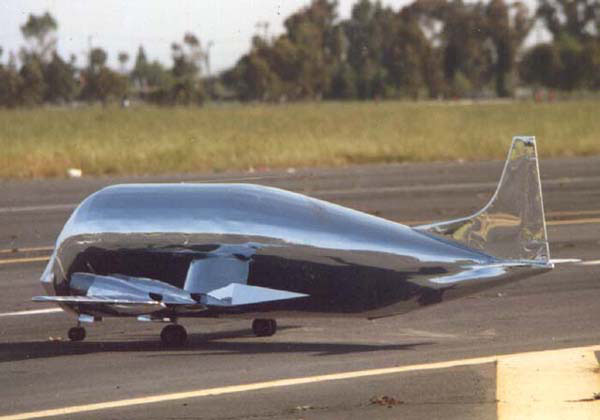
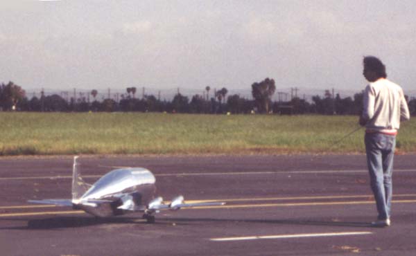 If
you can't see Dan's knees ashakin', it's because this photo was taken using
special high speed photography. We were both pretty nervous at this point,
almost two years of work about to take to the sky. We hoped. This is a good
size comparison, the top of the rudder is 29 inches up from the ground,
the top of the fuselage is almost two feet up from the ground! We called
the Super Guppy our big small model.
If
you can't see Dan's knees ashakin', it's because this photo was taken using
special high speed photography. We were both pretty nervous at this point,
almost two years of work about to take to the sky. We hoped. This is a good
size comparison, the top of the rudder is 29 inches up from the ground,
the top of the fuselage is almost two feet up from the ground! We called
the Super Guppy our big small model.(19K JPG image)
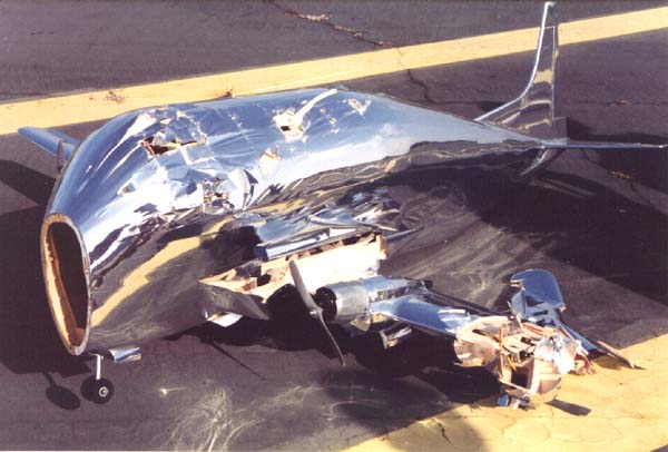 AARRGGHH!!
Why didn't we follow our first instinct?!! At this point we were pretty
discouraged. We had to sit back and take a look at what happened and why.
Luckily we video taped the test flight and were able to go back and analize
what went wrong that caused the model to crash. We inflicted much pain on
ourselves by viewing the crash many times. We determined that the airplane
was tail-heavy. Radically so. It had the characteristic excessive pitch
sensitivity seen in the wild pitch up imediately after lift-off. After taking
a second look at the actual damage, which was limited to the left wing panel
from the battered outer nacelle to the wing tip, and partially crushed bulkheads
on the front top portion of the fuselage. Some of the sheeting on the fuselage
was of course broken and gouged.
AARRGGHH!!
Why didn't we follow our first instinct?!! At this point we were pretty
discouraged. We had to sit back and take a look at what happened and why.
Luckily we video taped the test flight and were able to go back and analize
what went wrong that caused the model to crash. We inflicted much pain on
ourselves by viewing the crash many times. We determined that the airplane
was tail-heavy. Radically so. It had the characteristic excessive pitch
sensitivity seen in the wild pitch up imediately after lift-off. After taking
a second look at the actual damage, which was limited to the left wing panel
from the battered outer nacelle to the wing tip, and partially crushed bulkheads
on the front top portion of the fuselage. Some of the sheeting on the fuselage
was of course broken and gouged.Once the damaged sheeting was removed, it was a simple matter to repair the bulkheads, replace the broken stringers and resheet the fuselage. The wing from the right wing tip to the number one nacelle was perfect, we built another full left wing panel in anticipation of cutting off the left wing panel and cutting away the number two nacelle to be glued to the new wing panel and build a new number one nacelle. We later decided to replace only the broken portions of the wing. The new outer portion of the wing was butted glued to the rest of the wing and fiberglass reinforced. The joint was under the number one nacelle keeping it mostly hidden from view.
(39K JPG image)
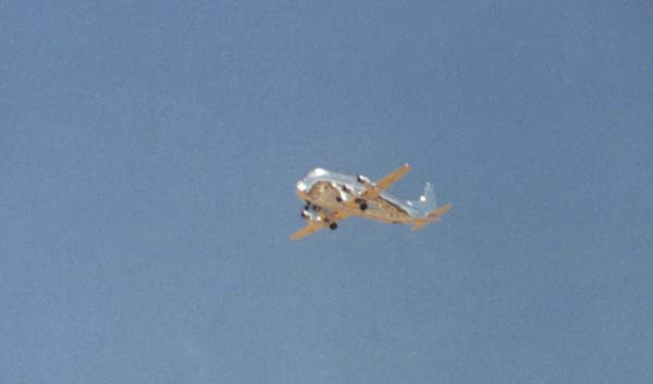
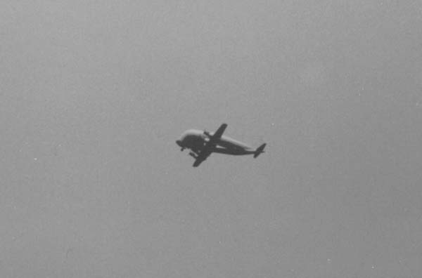 After
two months...Success!! In this recently declassified Russian spy photo,
the Sooper Guppinski is seen in the skies over Moscow, no doubt ferrying
parts of the Concordski. Actully the rebalanced model flew very smoothly.
A little down trim was needed and the Guppy flew hands off straight and
level. Some rudder was needed to co-ordinate the turns, with a small amount
of rudder held in during the turns.
After
two months...Success!! In this recently declassified Russian spy photo,
the Sooper Guppinski is seen in the skies over Moscow, no doubt ferrying
parts of the Concordski. Actully the rebalanced model flew very smoothly.
A little down trim was needed and the Guppy flew hands off straight and
level. Some rudder was needed to co-ordinate the turns, with a small amount
of rudder held in during the turns.We came up with a unique solution to counteract any possible problems with p-factor or torque the motors produced(geared electric motors do produce a fair amount of torque). The motors were mounted with zero down and right thrusts. After testing and synching the motors, we mounted the strongest motor in the #1 position (starting from the left outboard nacelle), the second strongest in the #4 position, 3rd strogest in the #2 postion and the weakest in the #3 position. We figured that having slightly more thrust on the left side of the airplane would negate any tendancies for the torque of the four motors to pull the airplane to the left, and it did. The sight and sound of the Super Guppy flying above was most satisifying.
(8K JPG image)
 These
series of pictures were taken at the Western Regional Scale Masters Qualifier.
We competed in the new Team Scale category. The guppy was an instant success.
We were one of the first to fly Saturday morning and had the sky to ourselves.
No one wanted to fly at the same time as the Guppy because as we later found
out, they all wanted to see the Guppy fly, at least the first time. I spoke
with one of the flight judges during our second round of flying, who was
glad to be judging the Guppy because as he put it, "Last round, I had
a hard time keeping an eye on the airplane I was supposed to be judging!"
These
series of pictures were taken at the Western Regional Scale Masters Qualifier.
We competed in the new Team Scale category. The guppy was an instant success.
We were one of the first to fly Saturday morning and had the sky to ourselves.
No one wanted to fly at the same time as the Guppy because as we later found
out, they all wanted to see the Guppy fly, at least the first time. I spoke
with one of the flight judges during our second round of flying, who was
glad to be judging the Guppy because as he put it, "Last round, I had
a hard time keeping an eye on the airplane I was supposed to be judging!"(10K JPG image)
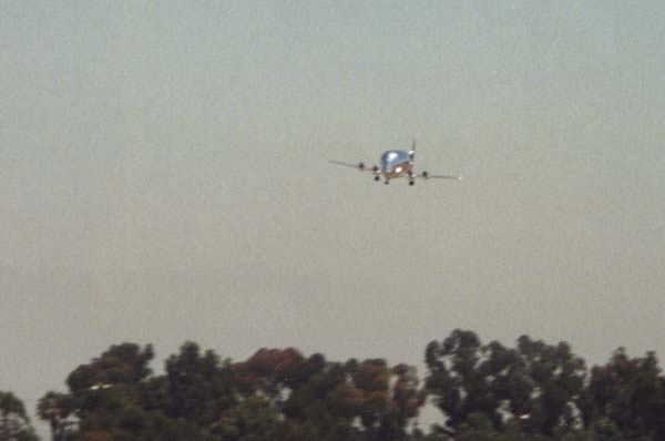 The
Guppy is seen here on final approach prior to landing. Some power was needed
for the approach, the drag from the fuselage and four propellers at idle
was enormous, giving the Guppy the glide ratio of your car keys. No matter
how many spectators were present, or how limited their knowledge of R/C,
the flying field always became ghostly still for the Guppy's landing.
The
Guppy is seen here on final approach prior to landing. Some power was needed
for the approach, the drag from the fuselage and four propellers at idle
was enormous, giving the Guppy the glide ratio of your car keys. No matter
how many spectators were present, or how limited their knowledge of R/C,
the flying field always became ghostly still for the Guppy's landing.(14K JPG image)
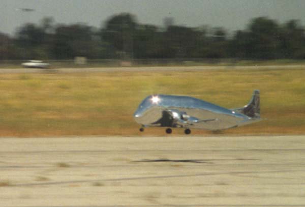 Dan's
about to "grease" on another landing. At about 2-3 feet the power
is brought to idle and flare for landing. The ground handling on the Guppy
proved to be impecable during both the take-off run and landing roll-out.
Although Team Scale wasn't then a category in the Nationals, we were invinted
to fly in the noontime demonstration. We were of course quite flattered
by the offer. We felt a little guilty at first with the amount of interest
the Guppy generated over other models present at the contest, both at the
contest and in later magazine coverage of the contest. But then we came
to the conclusion that "That's racing, you run what you brung."
Our project was getting the amount of recognition it deserved for the amount
of effort put into it.
Dan's
about to "grease" on another landing. At about 2-3 feet the power
is brought to idle and flare for landing. The ground handling on the Guppy
proved to be impecable during both the take-off run and landing roll-out.
Although Team Scale wasn't then a category in the Nationals, we were invinted
to fly in the noontime demonstration. We were of course quite flattered
by the offer. We felt a little guilty at first with the amount of interest
the Guppy generated over other models present at the contest, both at the
contest and in later magazine coverage of the contest. But then we came
to the conclusion that "That's racing, you run what you brung."
Our project was getting the amount of recognition it deserved for the amount
of effort put into it.(17K JPG image)
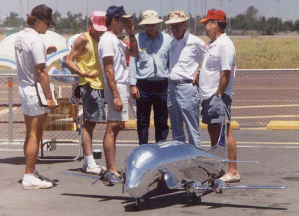 Once
again the famiiar sight of bewildered onlookers. Seen in this photo taken
at the Western Regional Scale Masters Qualifier from the left is; unknown
Flight Judge, Dan, Author, unknown Flight Judge, Dick S., Dad Jan. The guys
yukkin' it up have seen the Guppy fly before. Scale Model Research's Bob
Banka's jaw almost hit the sidewalk when we told him the Guppy weighed thirteen
pounds.Compare the size of the fuselage with the size of the wing's shadow
on the ground.
Once
again the famiiar sight of bewildered onlookers. Seen in this photo taken
at the Western Regional Scale Masters Qualifier from the left is; unknown
Flight Judge, Dan, Author, unknown Flight Judge, Dick S., Dad Jan. The guys
yukkin' it up have seen the Guppy fly before. Scale Model Research's Bob
Banka's jaw almost hit the sidewalk when we told him the Guppy weighed thirteen
pounds.Compare the size of the fuselage with the size of the wing's shadow
on the ground.(43K JPG image)
 The
Super Guppy is seen here on display at the 1995 Scale Masters Championships.
The promoters of the contest thought it would add a nice touch to have the
Guppy on display while the contestants' airplanes were being static judged.
This was in addition to being asked to fly as a part of the lunchtime demonstration
show. We felt doubly honored.We spent the most of the day at the static
judging, talking with the other contestants. The Guppy proved to be a good
conversation starter, and a great way to meet many new friends who share
a common love for the hobby.
The
Super Guppy is seen here on display at the 1995 Scale Masters Championships.
The promoters of the contest thought it would add a nice touch to have the
Guppy on display while the contestants' airplanes were being static judged.
This was in addition to being asked to fly as a part of the lunchtime demonstration
show. We felt doubly honored.We spent the most of the day at the static
judging, talking with the other contestants. The Guppy proved to be a good
conversation starter, and a great way to meet many new friends who share
a common love for the hobby.(27K JPG image)
 Finally,
it looks like a Super Guppy. The most recent additions include the nose
section, cowls and spinners. The lightest way to build the removable nose
section would be to construct a light wooden framework with a vacu-formed
plastic nose "facade" glued to. This meant a plug would have to
be made for pulling the plastic. We used a plywood frame with foam filler
blocks carved to shape. The windows were 1/32" birch plywood cut to
the proper size and glued into place. The plug was the glassed and sanded
to a smooth finish. The cowls were carved from a plywood and balsa sandwich.
Finally,
it looks like a Super Guppy. The most recent additions include the nose
section, cowls and spinners. The lightest way to build the removable nose
section would be to construct a light wooden framework with a vacu-formed
plastic nose "facade" glued to. This meant a plug would have to
be made for pulling the plastic. We used a plywood frame with foam filler
blocks carved to shape. The windows were 1/32" birch plywood cut to
the proper size and glued into place. The plug was the glassed and sanded
to a smooth finish. The cowls were carved from a plywood and balsa sandwich.The cockpit plug was sanded smooth and glassed. We differed here for the vacu-forming plugs from the nose section. We waxed the plug and using an organic molding compound, made two female molds. It took a little experimenting to get the proper technique for making usable molds. In next step, we poured plaster of paris into our female molds, tapped for bubbles and waited for the plaster to harden. Plain plaster of paris works very well for vacu-forming as no mold release is needed. As always when molding plastic, the cleaner the mold is, the clearer the plastic will be. Boiling the plastic during the heating process, and junk on the mold during the actual molding, are what most junks up plastic.
(38K JPG image)
Movies
 This
video was shot of the Guppy's first successful test flight. Dan won the
coin toss for the first test flight which resulted in the crash(through
no fault of his own), so now it was my turn to try my hand at the helm.
I let the Guppy build up speed on the take off roll... it lifted off by
itself and began a gentle climb-out, with only minor trim adjustments, flying
as if that's what it wanted to do all along. This solved the problem we
had with limited rotation angle. It's a probably a good thing the Guppy
flew as well as it did, because I was pretty nervous. The Free Flight guys
flying across the hobby area of Mile Square Park certainly got quite a show
that day.
This
video was shot of the Guppy's first successful test flight. Dan won the
coin toss for the first test flight which resulted in the crash(through
no fault of his own), so now it was my turn to try my hand at the helm.
I let the Guppy build up speed on the take off roll... it lifted off by
itself and began a gentle climb-out, with only minor trim adjustments, flying
as if that's what it wanted to do all along. This solved the problem we
had with limited rotation angle. It's a probably a good thing the Guppy
flew as well as it did, because I was pretty nervous. The Free Flight guys
flying across the hobby area of Mile Square Park certainly got quite a show
that day.(1655K QuickTime video)
 The
Guppy is seen during an overhead flyby. The sound of the geared electric
motors, combined with the slow speed at which the airplane flew, was better
than we could have hoped. The motors held their sync, never missing a beat.
There was some question in out minds before this flight regarding the small
size of the control surfaces, and how efective they would be. It turned
out to be not a problem at all. The control in all axis was good without
being sensitive. The Guppy took longer to build than we had anticipated,
was more work than had been planned, caused much too many headaches, and
reaped for both of us, more rewards personally, than all of the problems
combined. The Guppy steals even the best Mustang's thunder.
The
Guppy is seen during an overhead flyby. The sound of the geared electric
motors, combined with the slow speed at which the airplane flew, was better
than we could have hoped. The motors held their sync, never missing a beat.
There was some question in out minds before this flight regarding the small
size of the control surfaces, and how efective they would be. It turned
out to be not a problem at all. The control in all axis was good without
being sensitive. The Guppy took longer to build than we had anticipated,
was more work than had been planned, caused much too many headaches, and
reaped for both of us, more rewards personally, than all of the problems
combined. The Guppy steals even the best Mustang's thunder.(1354K QuickTime video)
Link here for Mac users having problems viewing movies. Use the Indeo Video 3.2 for Mac that installs Indeo version 3.22.24.09 for Mac 6.0.7 or later with QuickTime.
Comments or Questions? Email me
Copyright © 2006 Daren Savage
All Rights Reserved